
Outline
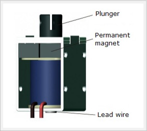
A magnetic latching solenoid is equipped with a permanent magnet that keeps the plunger in position magnetically when under no other force. With the internal permanent magnet maintaining attachment, only consuming power to reinstate attraction.
*The explanation of solenoids below is limited to our company’s products.
Applications
Magnetic latching solenoids are widely used for Home, daily equipment and Security such as Electric locks, ATM, Coin Lockers and other mechanisms which require long-term attachment.

Security
Features
Magnetic latching solenoids are equipped with permanent magnets so during use,
1. The pull force when de-energized
2. The electric current direction
3. The magnetic holding force
4. The return load and electric power
must be taken into consideration.
The de-energized pull force
The de-energized pull force refers to the pulling force applied to the plunger by the permanent magnet when the solenoid is de-energized.
The electric current direction
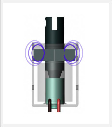
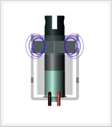
Similar to how magnets have N and S poles, a magnetic latching solenoid’s N and S poles are decided by the electric current direction. When under a pull force a current direction that does not repel the permanent magnet is necessary.
 The current direction is listed in the catalog. For the above example, a positive(+) red lead and a negative(-) black lead is the correct current direction for suction.
The magnetic holding force
When the plunger comes into contact with the fixed core, even if the power is cut the considerable force of the permanent magnet maintains the retracted plunger position.
The return load and electric power
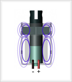
In order for the plunger to return, a current opposite of the above diagram is applied to repel the permanent magnet.
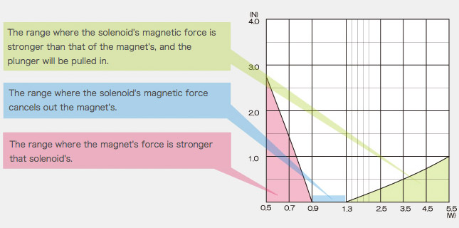
Electric power just enough to cancel the magnetic force of the magnet is necessary. If not enough power is applied, the magnetic force will not be cancelled, and if too much power is applied the solenoid’s magnetic force will win out over the magnet’s and end up pulling the plunger in.
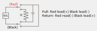
Because the resistor, R, in the diagram above can dissipate a lot of power at the same voltage as when energized, the power is adjusted by mediating the resistance. Because the plunger does not return to its original position automatically – the return takes place when the magnetic force of the permanent magnet is negated – during use, a load must be applied to the plunger taking into account the pull force when de-energized.
An explanation of the graph
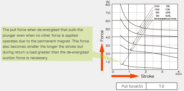
A magnetic latching solenoid’s pull force changes with the electric power applied just like a standard solenoid. The chart to the right from the catalog displays the pull force – stroke relationship for various power inputs.
The magnetic holding force is the force of the magnet that maintains the position of the plunger in contact with the fixed core when no other force is applied. Regardless of the current value or electric power, all magnetic latching solenoids of this size have the same magnetic holding force. The chart to the right is listed in the catalog.
The graph shows the relationship between the magnetic holding force and the electric power necessary to return the plunger.
The pull force when de-energized that pulls the plunger even when no other force is applied operates due to the permanent magnet. This force also becomes smaller the longer the stroke but during return a load greater than the de-energized suction force is necessary.
The magnetic holding force is the force of the magnet that maintains the position of the plunger in contact with the fixed core when no other force is applied.
Regardless of the current value or electric power, all magnetic latching solenoids of this size have the same magnetic holding force.
The chart to the right is listed in the catalog.
For example, if a magnetic latching solenoid with a resistance of 38Ω at 24V DC were in the range to return the plunger as shown in the graph, From:
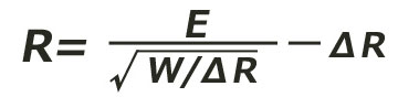 *△R is resistance of solenoid
(Using the graph to the right as an example, E=DC24V、P=09.W〜1.3W) a resistance R of 118Ω〜92Ω can be calculated.
A solenoid’s return is based on offsetting the force of the permanent magnet so the relationship may not quite match in the table to the right due to environmental factors such as temperature variation. Please give due consideration to this when setting the return load during actual use.
Product Lineup
| Model No. | Holding force(N) (non-voltage) |
D (mm) |
W (mm) |
H (mm) |
Max stroke (mm) |
Nominal stroke (mm) |
Force(N) Nominal stroke 50%Duty |
Force(N) Nominal stroke 6%Duty |
Price | CAD DATA |
Details |
 CD0730 CD0730 |
6 | 14.0 | 16.0 | 30.0 | 5 | 4 | 1.40 | 4.50 | $16.66 | 2D(DXF) 3D(IGES) 3D(X_B) 3D(STEP) |
 |
 CD0740 CD0740 |
7 | 16.0 | 18.0 | 40.0 | 8 | 5 | 2.65 | 6.90 | $19.30 | 2D(DXF) 3D(IGES) 3D(X_B) 3D(STEP) |
|
 CD1037 CD1037 |
16 | 21.5 | 26.0 | 37.0 | 8 | 4 | 4.20 | 15.00 | $20.11 | 2D(DXF) 3D(IGES) 3D(X_B) 3D(STEP) |
|
 CD1240 CD1240 |
10.5 | 24.0 | 29.0 | 40.0 | 6 | 3 | 5.66 | 16.70 | $21.23 | 2D(DXF) 3D(IGES) 3D(X_B) 3D(STEP) |
|